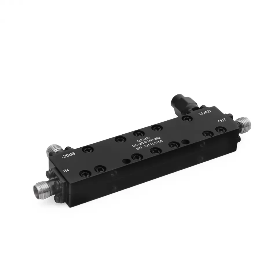
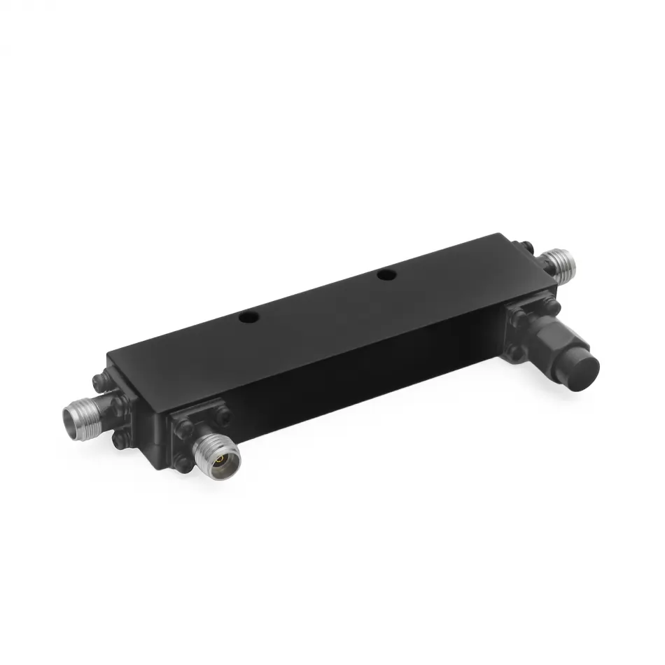


RF directional coupler 20 dB designed for professional test and measurement, power monitoring and signal sampling applications in microwave and mmWave systems. The component is intended for RF laboratories, test benches and automated test systems where stable performance over a wide frequency range is required.
Model DC-20-0140-292 operates over an extended frequency range from 1 to 40 GHz and features a 50 Ω coaxial interface with 2.92mm female (K) connectors, suitable for integration in broadband RF signal chains up to 40 GHz. Compliance with MIL-STD-348A ensures mechanical compatibility with high-performance laboratory instrumentation and cabling.
The nominal 20 dB coupling allows a significant portion of the signal on the main line to be sampled, making this coupler suitable for direct connection to power meters and RF monitoring equipment. The device maintains a VSWR ≤ 1.70 across the full operating band and a directivity ≥ 10 dB, enabling reliable forward and reflected power measurements.
Insertion loss on the main line is limited to 2.2 dB, minimizing the impact of the coupler on the RF system. Coupling sensitivity is kept within ±1.5 dB, contributing to measurement repeatability over the entire 1–40 GHz frequency range.
The directional coupler supports a continuous input power of up to 20 W, making it suitable for a wide range of laboratory and production test applications. The mechanical design is optimized for professional RF environments, featuring an aluminum alloy housing and stainless-steel connectors.
The component is rated for operation over a temperature range of -40 °C to +85 °C and complies with RoHS 3 and REACH directives, simplifying integration into systems intended for regulated markets.
A 20 dB directional coupler is generally selected when a more moderate signal sample is required at the coupled port, providing a good balance between measurement level and loading of the main transmission line. It is suitable for broadband amplifier characterization, RF power monitoring and functional verification where the impact on the main signal path must be limited.
This model is commonly used in automated test equipment (ATE), radar systems, telecommunications and measurement applications up to 40 GHz, where 2.92mm connectors represent the standard interface for high-frequency performance and repeatable measurements.
The datasheet includes typical S-parameter measurement curves for the 20 dB configuration across the full frequency range, supporting performance evaluation and system integration in broadband RF applications.
 English
  Italiano
  Deutsch
  Français
  Español
  DCK-001 -
10dB
DCK-001 -
10dB  DCK-004 -
30dB
DCK-004 -
30dB 

