Noise generator diodes
More informations
All the materials generate noise and the noise is proportional to its temperature starting from 0°K (-273°C). The noise depends on the chaotic movements of the electrons, the thermal noise is known as white noise (from optical physics) as it fills the whole spectrum. From an electronics point of view the noise causes big limitations to our devices for example amplifiers, instruments, radars, receivers, electro-medical, etc... A very simple example is the sensitivity limitation of receivers caused by the noise.
Although the noise causes problems and limitations, it will be explained how in some cases, if it is artificially generated, it can even improve our electronic devices (see dithering) or help to do some
tests, a calibrated noise source is a very important tool in our labs.
NOISE GENERATORS: The first noise generators used noble gas such as Argon with 15.3dBENR, Neon with 18.5dBENR, Helium with 21dBENR and were born in order to test the first radar systems in the 1940s. Another method to generate noise is to use hot and cold resistors, mainly used in research labs with very high precision, this technique due to its complexity is used only in physic laboratories or in calibration centers. Today the most used noise generators are special diodes, noise diodes. A reverse polarized diode until it reaches the avalanche effect is an example of noise generator (see Zener diodes). Unlike Zener diodes, the noise diodes are doped and developed to cover a wider band (low Cj) with an output level really flat and more stable.
OUTPUT LEVEL: For noise source applications the output level cannot be indicated as for other signal generators. Signal generators, transmitters etc...; have the output level indication in mV, dBm, W etc... If you have a 100 to 200MHz sweep signal generator we say that the output level is for example -10dBm, the amplitude of -10dBm is swept from 100 to 200MHz but it is not simultaneously in the whole frequency range.
In the case of noise sources the amplitude is simultaneously on the entire frequency range, this means that the amplitude is defined in dBm/Hz power spectral density, or in ENR excess noise ratio. ENR means the ratio in decibel of the output noise between the ON and OFF state of the diode, in the OFF state the diode has only -174dBm/Hz which is the output level generated by a resistor at 290°K (about 17 °C). For example, if we have a power spectral density of -142dBm/Hz it means that (174 - 142 = 32) so the ENR is 32 dB. If the bandwidth is 10Hz the noise power is -132dBm/10Hz if the bandwidth is 10KHz the noise power is -102dBm/10KHz.
See the example in a spectrum analyzer the noise level changes depending on the used IF bandwidth.
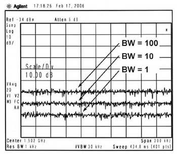 |
3 values of IF bandwidth (BW), as it narrows the bandwidth the noise level down by law 10log BW, examples: |
Some applications for noise source diodes
|
DITHERING |
AUDIO AND ULTRASONIC TEST |
|
NOISE FIGURE MEASURES |
SPECTRUM ANALYZER CALIBRATION |
|
TESTS ON RECEIVERS |
NPR DISTORTION MEASURES |
|
FADING SIMULATOR |
FILTERS AND ANTENNAS TESTS |
| RADIO ASTRONOMY | ELECTROMAGNETC SUSCEPTIBILITY |
|
GAIN / BANDWIDTH MEASURES |
No products found