487264419F Alcatel |
|
|---|---|
Sub-harmonic UP/DOWN mixer, +15 dBm, 17.6 - 24.4 GHz
487264419F
Order code: MIXER-23G-A
Product conditions: N-
|
|
-
17.6 - 24.4 GHz
-
8.8 - 12.6 GHz
-
dc - 2.5 GHz
-
15 dBm
-
16 dB
-
SMA female / 2.92mm (K) female
-
double-balanced
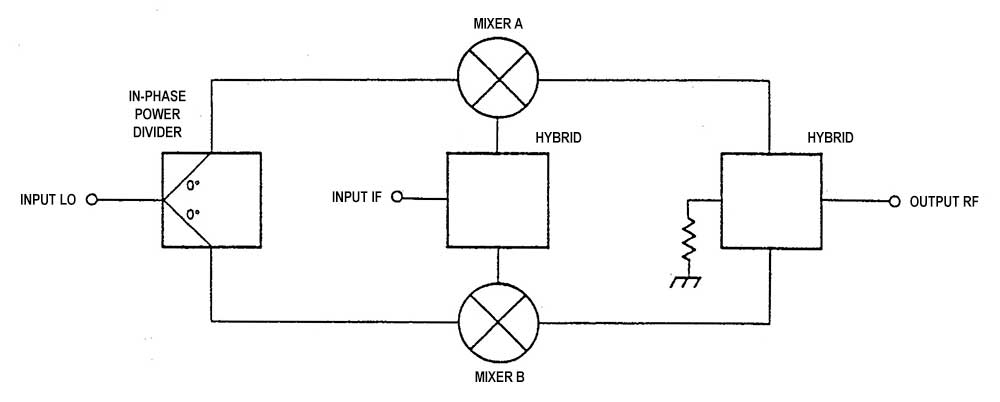
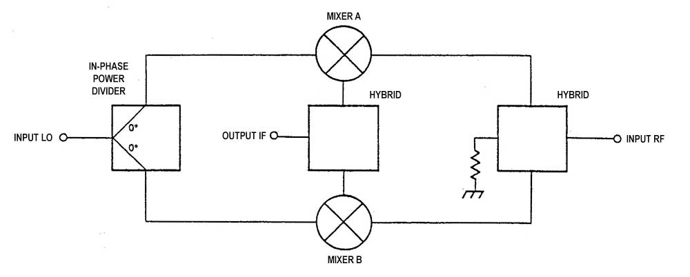
This passive mixer can be used both for down-converter applications (from 23 GHz to IF), in this case the RF port will be an input connector while the IF port will be the output of the converted signal, and up-converter (from IF to 23 GHz) in this case the RF port will provide the signal output while the IF port will be the input of the signal to be converted. The LO signal level is approximately +14 / +15 dBm or 25-30 mW and the conversion loss from 11 to 17 dB for both down and up converters. The LO and IF connectors are SMA female while the RF connector is a K male (or PC2.92, precision series up to 40 GHz and compatible with SMA). The maximum recommended level of the IF and RF signals is up to 0 dBm (1 mW) to avoid compression problems, while the absolute maximum level for all ports is +20 dBm (100 mW). The mixer uses a circuit capable of duplicating the frequency of the LO signal in order to simplify the LO chain by using a halved LO frequency with respect to that normally required, and also ensures good attenuation of the LO signal on both the IF and RF ports.
SPECIFICATIONS:
- RF: 17.6 - 24.4 GHz
- LO: 8.8 - 12.6 GHz
- IF (-3dB): dc - 2.5 GHz (RF < 22.5 GHz)
dc - 800 MHz (RF > 22.5 GHz)
- LO level: +14 to +15 dBm
- Insertion loss: 11 to 17 dB
- Isolation (LO to IF): >50 dB (LO > 10.5 GHz)
>35 dB (LO < 10.5 GHz)
- Isolation (LOx2 to IF): >60 dB
- Isolation (LO to RF): >35 dB
- Isolation (LOx2 to RF): >50 dB
- Isolation (RF to IF): >25 dB (RF < 23 GHz)
>15 dB (RF > 23 GHz)
- Connectors (LO + IF): SMA female
(RF): K male (PC2.92mm 40 GHz precision version)
- Max. Input level: +20 dBm for all the ports
- 1 dB compression point (P1dB): +3 dBm (IF and LO ports)
- Test condition level (LO): +14.5 dBm
(IF or RF): -20 dBm
- Calculator for test frequency: RF = (LO x 2) - IF
IF = (LO x 2) - RF
- Dimensions: 34 x 33 x 16 mm (excluding connectors)
----------------------------------------------------------------------------------------------
BLOCK DIAGRAM OF THE UP CONVERTER
BLOCK DIAGRAM OF THE DOWN CONVERTER
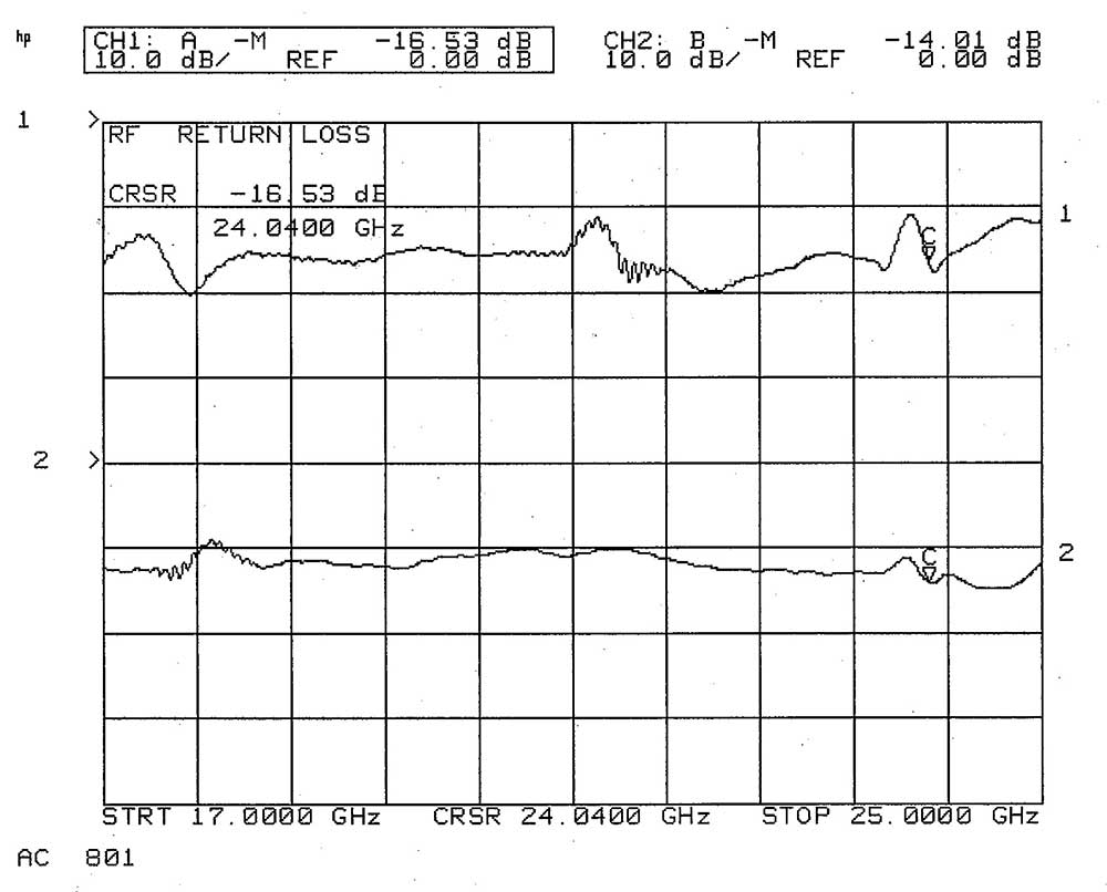
RETUN LOSS RF PORT
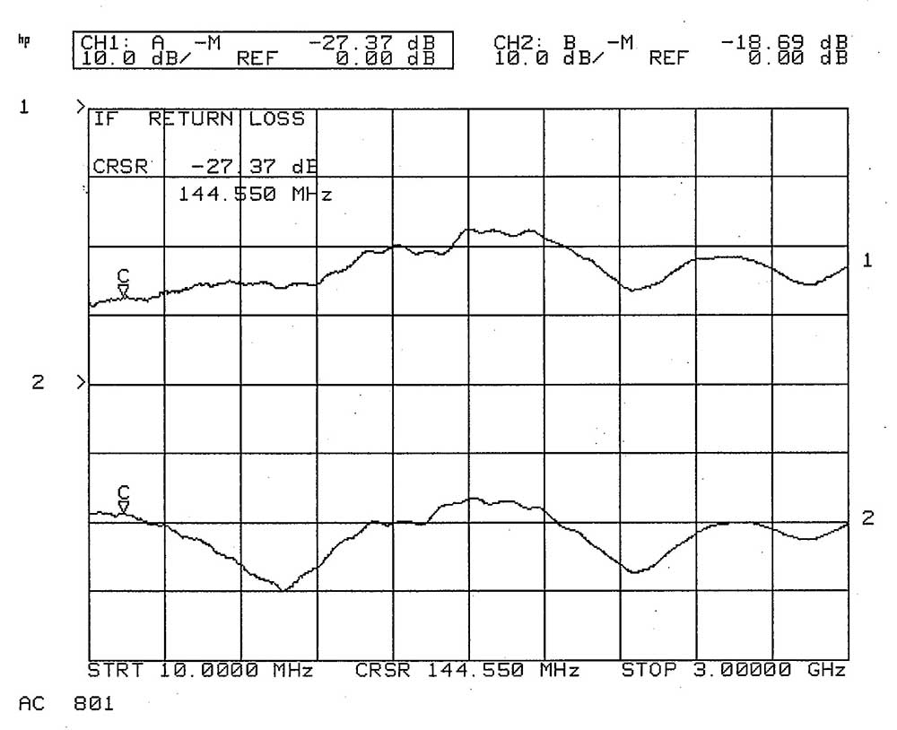
RETUN LOSS IF PORT
-
IT
-
85437090
-
50.00 g
-
No
-
Not available


