All these coils have been tested and characterized with our instrumentation: HP 4191A 1-1.000 MHz impedance analyzer, HP 4342A 22 KHz - 70 MHz precision Q meter and Racal 9383M RLC bridge.
Q value is referred to the measurement conditions (frequency and inductance values) and it is measured about at half of the inductance range.
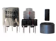
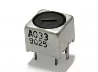
The electrical diagram has to be viewed by the pin side, it is also available the number of turns. The picture shows the complete coil and all its parts.
Coils with a parallel capacitor have also the auto-resonance value in MHz due to the internal capacitor, for these coils the maximum frequency is that stated, while the minimum frequency can be decreased by adding an external capacitor.
“MOLDED” indicates a different way of manufacturing of these coils, they are rugged, the turns are winded on a polypropylene support more resistant either to soldering and to mechanical torque and they are often use for VHF - UHF band, in “molded” coil the support has the purpose to keep the turns stable and separate to obtain the highest possible Q and thermal stability. The “c” symbol indicates the coil external size while in the picture there is the pins pitch.
After a long work of research of technical specifications, we believe that this can be an helpful aid in choosing a component that fits as possible different projects. The tests results have been collected directly in our lab so the specifications are often more complete than those provided by the manufacturers.
 |
HP 4191A
impedance analyzer, RLC, phase and Q meter 1 MHz - 1 GHz |
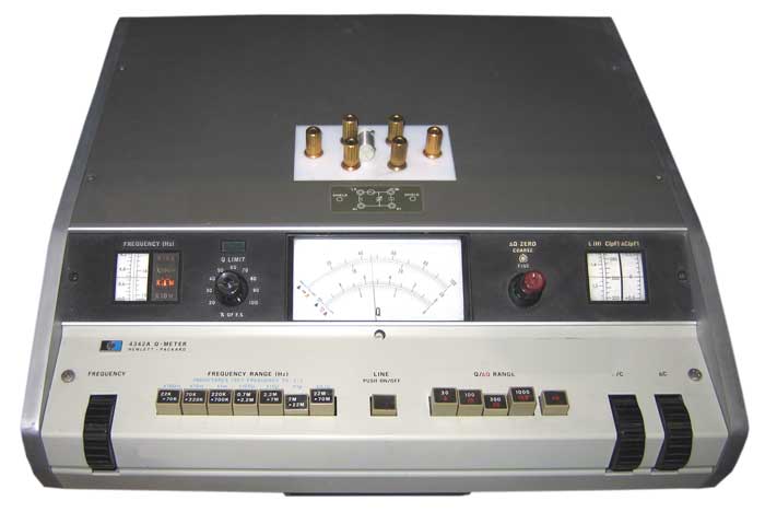 |
HP 4342A
high precision Q meter 22 KHz - 70 MHz |
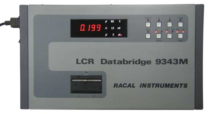 |
Racal 9343M
LCR universal bridge |